|
Wireless Set 52 Transmitter
Marconi WS No 52
|
|
Circuit Diagram, Service
Manual, Service
Information, Schematic Diagrams and Manuals |
|
For Repairing, Restoration and
Servicing of Vintage and Modern Electronic Equipment |
|
Manual and
Circuit
available
Details Below
As a Download
Click Here
|
|
Circuits
& Manuals
Military,
Radio, TV,
Amateur & Marine
World Wide Service
For
Lists Click Here
|
|
Use R/H scroll Bar
More information
below
Radio's For Sale
Click Here
Military and
Broadcast
Radio Ads Click
Here |
|
Military Radio Home
Click
Here If no Index to the left
|
The Canadian Marconi Transmitter No
52
Developed from the No 9 and No 9 Mk I sets and originally designated No 9 Mk II.
The No 52 Set was developed for Brigade / Division communications and principally used for Division rear-link
commands.
It could be a ground station or vehicle-mounted.
The principal improvements were in frequency range and RF output, making this unit far more successful than the No 9 Set it replaced.
The improved frequency coverage was achieved by the use of three bands.
The original No 9 Set had a single band from 1.875 to 5 MHz. |
|
The No 52 Set had 3 bands from 1.75 to
16 MHz.
It was used from 1944 until its replacement in the 1950s by the Larkspur C11/R210.
The Frequency Coverage
1.75 to 16 Mc/s in three bands.
Band 1 : - 1.75
to 4 Mc/s.
Band 2 : - 3.5 to 8 Mc/s.
Band 3 : - 7 to
16 Mc/s.
Flick frequency selection is available on transmitter and receiver.
The No 52 Set has three modes, low, medium and high, giving 2-4 15-20 18-30 45-75 and 75-100 Watts respectively. |
Manual and
Circuit
available
Details Below
As a Download
Click Here |
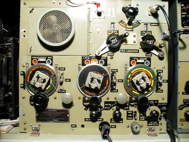
Wireless Set 52 Transmitter Marconi WS No 52
The 52 set Receiver and Transmitter information is somewhat integrated,
separating out the TX & Rx is not practical as individual pages contain reference to both.
I have a total of 31 pages Electrical and Mechanical Engineering Regulations, covering both Transmitter and Receiver.
Plus
31 pages on the Receiver only and 9 pages on the Transmitter only.
Total of 71 A4 Pages containing the following :-
Circuits Transmitter and Receiver
Basic layouts.
Typical meter readings.
Component lists.
Sender alignment.
Receiver Alignment RF & IF
Power Output Levels.
Resistance charts Measurement of resistance to chassis from various points.
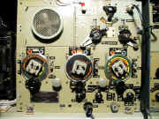
Pictures of front panels
Aerial socket parts.
Power supply circuit and layout
It is comprehensive and gives all the relevant information to renovate a 52 set Transmitter,
I used this manual to renovate my 52 Set.
|
The 52 Set Manual covers both the Transmitter and Receiver.
Manuals are Available
Worldwide as a Download.
Manual covering both the Transmitter &
Receiver 71 A4 pages worldwide.
( For all Payment Options )
( Please Click the Payment Links Below ) |
|
We do all we can to provide
the very best that is available for you.
But in the unlikely event that any data should not be as you expected.
A refund is always available. Kind Regards Allen and Alanna. |
|