|
AN/GRR-2 ANGRR2 Radio
Receiver
Hallicrafters SX-28-A SX28A
|
|
Circuit Diagram, Service
Manual, Service
Information, Schematic Diagrams and Manuals |
|
For Repairing, Restoration and
Servicing of Vintage and Modern Electronic Equipment |
|
Manual
Circuit and
Operating Instructions
available
Details Below
As a Download
Click Here
|
|
Circuits
& Manuals
Military,
Radio, TV,
Amateur & Marine
World Wide Service
For
Lists Click Here
|
|
Use R/H scroll Bar
More information
below
Radio's For Sale
Click Here
Military and
Broadcast
Radio Ads Click
Here |
|
Military Radio Home
Click
Here If no Index to the left
|
AN/GRR-2 Radio Receiver
Hallicrafters
SX-28-A
GENERAL.
Radio Receiver AN/GRR-2 (Hallicrafters Model SX-28-A) is a 15-tube superheterodyne receiver covering the frequency
range of 550 kilocycles (kc/s) to 42 megacycles (mc/s) in six bands.
It is designed to receive amplitude-modulated (a-m) or keyed continuous-wave (c-w) signals.
The receiver may be operated with the internal power supply from an a-c source, or from an external d-c source.
WEIGHTS AND DIMENSIONS.
The complete receiver weighs 78 pounds and is 16½ inches deep, 20 3/4 inches wide, and
10 3/4 inches high.
Packed for shipment the set weighs 135 pounds and is 21½ inches deep, 27 inches wide, and 15½ inches high.
FREQUENCY COVERAGE.
The six bands cover the following frequencies
550 kc to 1.6 mc/s 1.6 mc/s to 3.0 mc/s 3.0 mc/s to 5.8 mc/s
5.8 mc/s to 11 mc/s 11 mc/s to 21 mc/s 21 mc/s to 42 mc/s
All six bands are calibrated on the main tuning dial for direct reading, providing the band spread dial is set at 100 on the 0 to 100 scale.
The band spread knob may be used for vernier tuning on any part of the four highest frequency bands, but the scale is only calibrated for a portion of these four bands.
3.0- to 5.8-mc/s band 3,500 to 4,000 kc/s
5.8- to 11-mc/s band 7,000 to 7,300 kc/s
11- to 21-mc/s band 14,000 to 14,450 kc/s
21- to 42-mc/s band 28,000 to 30,000 kc/s
VALVES ( TUBES ) AND CIRCUITS.
The following tubes and circuits are used in Radio Receiver
AN/GRR-2:
R-f amplifier JAN6AB7 (V1)
JAN-6SK7 (V2)
A-v-c amplifier JAN-6B8 (V8)
A-n-l circuit JAN-6AB7 (V9) JAN-6H6 (V1O)
Mixer JAN-6SA7 (V3)
H-f oscillator JAN-6SA7 (V4)
B-f-o circuit JAN-6J5 (V11)
A-f amplifier JAN-6SC7 (V12) JAN-6V6GT (V13) JAN-6V6GT (V14)
I-f amplifier JAN-6L7 (V5)
JAN-6SK7 (V6)
Detector JAN-6B8 (V7)
Rectifier JAN-5Z3 (V15)
POWER REQUIREMENTS.
This receiver may be operated from either an a-c or d-c source.
For a-c operation the line voltage must be within the limits of 110 to 125 volts at 50 to 60 cycles.
A-c power consumption is 138 watts for a 117-volt, 60-cycle supply.
For d-c operation, a 6-volt, 4.8-ampere heater supply, and a 270-volt, 150-milliampere
high voltage supply are needed.
DC power consumption is 108 watts.
POWER OUTPUT.
The power output of the push-pull audio amplifier is approximately 8 watts into a 5,000-ohm load.
NORMAL PERFORMANCE CHARACTERISTICS.
Sensitivity.
The sensitivity of the receiver varies between the limits of 6 to 20 microvolts for a 500-milliwatt output over the entire range of the receiver.
Selectivity.
The selectivity of the receiver is determined by the band pass of the i-f circuits.
The SELECTIVITY control, in conjunction with the crystal-filter circuit, provides six degrees of selectivity.
The width of the band pass is variable from a few hundred cycles at SHARP CRYSTAL position, to approximately 25 kc on BROAD I.F., at .50 percent down on the selectivity curves.
Frequency Response.
The over-all audio-frequency response with the BASS switch at the IN position, the SELECTIVITY switch at BROAD I.F., and the TONE control at 9, is flat to within 2½ decibels (db) over the frequency range of 70 to 3,000 cycles.
Intermediate Frequency.
The i-f circuits are aligned to 455 kc, and the crystal filter has a natural frequency of 455 kc, plus or minus 5 kc. |
|
|
Manual
Circuit and
Operating Instructions
available
Details Below
As a Download
Click Here |
| The Manual Contains the
Following :-
Description.
General
Weights and dimensions
Frequency coverage
Tubes and circuits
Power requirements
Power output
Normal performance characteristics
Installation and operation.
Un packing Preparation for use Operation
Functioning of parts.
General
R-f amplifier
Mixer
H-f oscillator
I-f amplifier
Detector
Noise limiter
A-v-c amplifier
Audio amplifier
Beat-frequency oscillator
Power supply Maintenance.
Inspection
Lubrication
Replacement
Field adjustments
Trouble location chart
Voltage readings
Resistance measurements
Alignment procedure
Performance specifications
Moisture proofing and fungi proofing
Supplementary data. Maintenance parts list List of manufacturers
LIST OF ILLUSTRATIONS
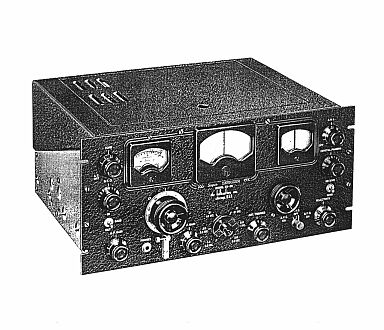
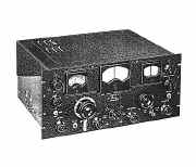
Radio Receiver AN/GRR-2
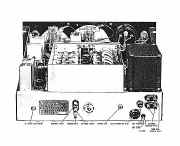
Radio Receiver AN/GRR-2, rear chassis apron
Radio Receiver AN/GRR-2, operating control panel.
I-f selectivity curves without crystal filter
Crystal selectivity curves
Effect of correct adjustment of CRYSTAL PHASING control
Radio Receiver AN/GRR-2, block diagram
Radio Receiver AN/GRR-2, top view of chassis
R-f amplifier, schematic
Mixer stage, schematic
High-frequency oscillator, schematic
First i-f amplifier, detector, and A.N.L., schematic
Crystal filter and second i-f amplifier, schematic
Automatic-volume-control amplifier, schematic
A-v-c curve taken at 3 megacycles
Audio amplifier, schematic
Effect of TONE control on audio fidelity at BROAD I.F. and SHARP I.F. positions of SELECTIVITY control, BASS switch at IN position
Audio frequency response with BASS switch IN and OUT, SELECTIVITY control at XTAL SHARP position
Beat-frequency oscillator, schematic
Power supply, schematic
Voltage readings
I-f aligning adjustments
R-f and oscillator adjustments
Radio Receiver AN/GRR-2, bottom view
Color code chart
Dimensional drawing
Radio Receiver AN/GRR-2, schematic |
|
|
Manual
Circuit and
Operating Instructions
available
Details Below
As a Download
Click Here |
AN/GRR-2 Radio Receiver
Hallicrafters
SX-28-A
Manuals are Available
Worldwide as
a Download.
Manual containing 75 pages
including the Circuits with Component lists and layouts.
Manual 75 A4 pages worldwide : -
( For all Payment Options )
( Please Click the Payment Links Below ). |
|
We do all we can to provide
the very best that is available for you.
But in the unlikely event that any data should not be as you expected.
A refund is always available. Kind Regards Allen and Alanna. |
|