|
AN/ART13 AN/ART13A
AN/ART13B
AN/ART-13 AN/ART-13A
AN/ART-13B Collins Radio Transmitter Transmitting
Set Download
|
|
Circuit Diagram, Service
Manual, Service
Information, Schematic Diagrams and Manuals |
|
For Repairing, Restoration and
Servicing of Vintage and Modern Electronic Equipment |
|
Manual with
Circuit
and Layout Images
available
Details Below
As a Download
Click Here
|
|
Circuits
& Manuals
Military,
Radio, TV,
Amateur & Marine
World Wide Service
For
Lists Click Here
|
|
Use R/H scroll Bar
More information
below
Radio's For Sale
Click Here
Military and
Broadcast
Radio Ads Click
Here |
|
Military Radio Home
Click
Here If no Index to the left
|
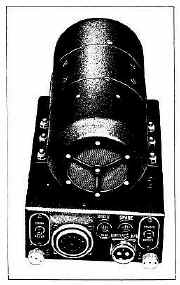
GENERAL DESCRIPTION OF EQUIPMENT.
Collins
Radio Transmitting Sets AN/ART-13A and AN/ART-13B are medium power, aircraft radio transmitters, designed to provide radio communication by
voice, modulated continuous wave telegraphy (MCW), or continuous wave telegraphy (CW).
Either a carbon or dynamic microphone may be used for voice emission.
The audio system is
capable of modulating the carrier (100 watts nominal) at least 90 percent for MCW or Voice emission.
When operating with CW or MCW emission, entirely satisfactory performance will be obtained for keying speeds up to 30 words per minute.
Transmission frequencies differ between the Models AN/ART-13A and AN/ART-13B as outlined in the
manual.
Shifting from one transmission to another can be accomplished by the conventional method of “hand-positioning” the controls or by using the built-in automatic shifting mechanism known as the “Autotune”.
This automatic mechanism is also utilized to provide remote control of functions required to shift transmission
frequency. |
|
|
|
The Manual Consists
of the Following :-
GENERAL DESCRIPTION
Equipment Supplied
Equipment Required but Not Supplied
General Description of Equipment
Transmitters
Dynamotor Unit
Control Units
Control Panel
Antenna Loading Unit
Antenna Shunt Capacitor
Similar Equipment
Interconnection of Radio Transmitting Set AN/ART-13A with
Radio Receiving Set AN/ARR-11 to Form Complete Radio Set
AN/ARC-8
Interchangeability of Major Units
Abbreviations
Symbol Designation
INSTALLATION AND ADJUSTMENT
Uncrating
Transmitter
Dynamotor Crate
Control Unit
Antenna Loading Unit
Antenna Shunt Capacitor
Preparation for installation
Mechanical inspection
Bench Test
Installation
Transmitter
Dynamotor Unit
Antenna Loading Unit
Control Unit
Control Panel
Antenna Shunt Capacitor and Switch
Oscillator 0-17/ART-13A and Panel MX-128/ART-13
Oscillator CDA-T Inter-Unit Connections
Inspection and Test after Installation
Adjustments
Use of Calibration Tables
Procedures for Setting the Controls of Radio Transmitter Set
AN/ART-13A (Manual or Autotune Operation)
Simplified Procedure for Setting the Controls
OPERATION
Starting and Stopping the Equipment
To Start
To Stop
Operation During Normal Use
Corrective Measures If Normal Operation Is Not Obtained
Fuse or Circuit Breaker Failure
Remote Control Unit or Cable Failure
Tube Failures
Autotune Failure
Antenna Loading Unit Failure
Vacuum Switch Failure
Cold Weather Failure
THEORY OF OPERATION
Description of Operation
General
Origin of Carrier Frequency
Modulation
First Audio Amplifier, Audio Driver, and Modulator
MCW Oscillator
Power Amplification and Antenna Coupling
Antennas
Sidetone Amplifier
Calibration Frequency Indicator ("CFI") Unit
Generation
Output
Detailed Analysis of Major Circuits
Power Control Circuits
Filament Circuits
High Voltage Circuits
Emission Selection and Carrier Control
Audio Circuits
“CFI" Calibration Oscillator Unit
Radio-Frequency Circuits Radio Transmitting Set AN/ART-13A
Radio-Frequency Circuits Radio Transmitting Set AN/ART-13B
The Autotune System
Mechanical Characteristics
Electrical Characteristics
Operation Cycle of Autotune Mechanism
Functions Performed by the Autotune System
MAINTENANCE
Inspections
Pre-Flight Inspection
Daily inspection
100-Hour Inspection
Trouble Shooting in the Plane
Simplified Trouble Shooting on Installed Equipment
Tube Checking and Replacement
Trouble Shooting at Repair Station
Trouble Shooting Table
Removing and Servicing Major Assemblies—Obtaining Access to Parts
Maintenance of Autotune Mechanism
Lubrication
Synchronization Check
Synchronization
Autotune Positioning Mechanism
Checking and Adjusting Limit Switches
Replaceable Parts of Autotune Mechanism
Replacing Autotune Parts
Alignment of VFO Radio Frequency Circuits Model AN/ART-13A
Low-Frequency Oscillator Alignment
High-Frequency Oscillator Alignment (Using “CFI”)
High-Frequency Oscillator Alignment (Using External Frequency
Standard)
Frequency Multiplier Alignment
Alignment of Crystal-Controlled Radio Frequency Circuits Model
AN/ART-13B
Low-Frequency Oscillator Alignment
High Frequency Oscillator Alignment
Alignment of CFI Unit
General Calibration Instructions
Precision Calibration
Approximate Calibration Adjusting of MCW Oscillator
Replacing and Adjusting Vacuum Contact S116
SUPPLEMENTARY DATA
Calibration Tables 6-9 and 6-10
Tables of Approximate Control Settings (for Antenna Tuning and
Loading) — Table 6-11
General Specifications of Equipment
Range of Available Transmission Frequencies
Frequency Stability
Antenna Requirements
R-F Power Output
Modulation
Power Input Requirements
Dynamotor
Tube Complement
Audio Input impedance
Overall Audio Frequency Response
Sidetone Output
Audio Input
Noise Level
Audio Distortion
Sidetone Distortion
Resistance Measurements of Autotune Motor
PARTS CATALOGUE
DRAWINGS
AN/ART-13A Equipment Supplied
AN/ART-13B Equipment Supplied
Equipment Required but Not Supplied
Vacuum Tube Complement
Power Input Requirements
Required Antenna Characteristics
Interchangeability of Major Units
Use of Antenna Shunt Capacitor with Antennas of Different
Lengths
CDA-T Crystal Controlled Oscillator/Multiplier Operation
VFO-Oscillator/Multiplier Operation
Frequency Range Covered by Positions of High Frequency Tuning Control “A”
Function of Multi-Section Output Network Switch S113
Trouble Shooting on Installed Equipment
Trouble Shooting at Repair Station
Voltage-to-Ground from Vacuum Tube Terminals
Voltage-to-Ground from Cable Connector Terminals
Resistance-to-Ground from Vacuum Tube Terminals
Resistance-to-Ground from Cable Connector Terminals
Resistance-to-Ground from Tube and Connector Terminals CDA-T Unit
Replaceable Autotune Parts
Range of Available Transmission Frequencies in Low Frequency
Range
Range of Available Transmission Frequencies in High Frequency
Range
R-F Power Output
Power Input Requirements
Dynamotor Characteristics and Resistance Measurements
Vacuum Tube Complement
Sidetone Output
Resistance Measurements of Autotune Motor
Calibration of Low Frequency Oscillator (200 KC to 600 KC)
Calibration of High Frequency Oscillator (2000 KC to 18100 KC)
Tables of Approximate Dial Settings (for Antenna Tuning and
Loading)
LIST OF ILLUSTRATIONS
Radio Transmitting Set AN/ART-13A Major Assemblies
Radio Transmitting Set AN/ART-13B Major Assemblies
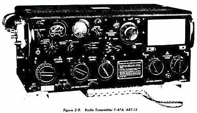
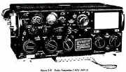
Radio Transmitter T-47A/ART-13
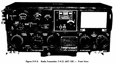
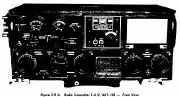
Radio Transmitter T-412/ART-13B-Front View
Radio Transmitter T-47A/ART-13 Units Removed
Radio Transmitter T-412/ART-13B and Removable Units
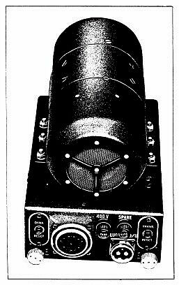
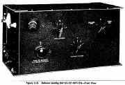
Dynamotor Unit DY-17/ART-13A
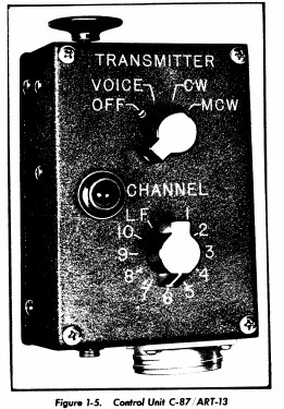
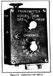
Control Unit C-87/ART-13
Control Panel C-405/A
Antenna Loading Unit CU-32/ART-13A Front View
Antenna Shunt Capacitor CU-24/ART-13
Tube Replacement Diagram
Tube Replacement Diagram AN/ART-13B
Microphone Selector Switch and Sidetone Output Switch
MCW-CFI Unit Top View
Transmitter and Mounting Plate MT-283/ART-13, shown with
Mounting Bases MT-284/ART-13 and MT-284A/ART-13
Dynamotor Unit DY-17/ART-13A with Mounting Plate MT-164/ART-13
Antenna Loading Unit CU-32/ART-13A with Mounting Base
MT-198/ART-13A
Control Unit C-87/ART-13 with Mounting Plate MT-163/ ART-l3
Illustration Showing Setting of Control “B” to 1114.1
Radio Transmitter T-47A/ART-13
Radio Transmitter T-412/ART-13B Front View
Antenna Loading Unit CU32/ART-13A Front View
Crystal Controlled Oscillator Unit (CDA-T) Front Side View
Radio Transmitting Set AN/ART-13A Block Diagram
Radio Transmitting Set AN/ART-13B Block Diagram
Power Control Circuits
Filament Circuits AN/ART-13A and AN/ART-13B
Filament Circuits AN/ART-13B
High Voltage Circuits
Emission Selection and Carrier Control Circuits AN/ART.13A
Emission Selection and Carrier Control Circuits AN/ART-13B
Speech Amplifier Circuits
Modulator Circuit
Sidetone Amplifier Circuit
MCW Oscillator Circuit
CFI Oscillator Circuit
VFO Low Frequency R-F Circuits AN/ART-13A
Low Frequency R-F Circuits Crystal Controlled Operation
AN/ART-13B
High Frequency R-F Circuits VFO Operation AN/ART-13A
High Frequency R-F Circuits Crystal-Controlled Operation
AN/ART-13B
Power Amplifier and High Frequency Output Circuits
Autotune Mechanism Mechanical Portion
Singleturn Autotune Unit (Type 96J) Left Side View
Singleturn Autotune Unit (Type 96J) Right Side View
Multiturn Autotune Unit (Type 96K) Left Side View
Multiturn Autotune Unit (Type 96K) Right Side View
Autotune Casting
Electrical Portion of Autotune System
Sequence of Autotune Operation
Tube Replacement Diagram AN/ART-I3A
Location of Brushes on Russell Dynamotor
Location of Brushes on General Electric Dynamotor
Initial Disassembly of Eicor Dynamotor
Exploded View of Eicor Dynamotor
Component Parts of Russell Dynamotor
Component Parts of General Electric Dynamotor
Radio Transmitter T-47A/ART-13 and Removable Units
Low Frequency Oscillator
Crystal-Controlled Oscillator Unit (CDA-T) Top View
High Frequency Oscillator Side View, Open
Frequency Multiplier
MCW-CFI Unit Top View
Keying Relay K102 and Vacuum Contact S116
Overall Audio Frequency Response Curve
Radio Transmitter T-47A/ART-13 Front View, Open
Radio Transmitter T-47A/ART-13 Top View, Cover Removed
Radio Transmitter T-4l2/ART-13B Top View, Cover Removed
Radio Transmitter T-47A/ART-13 Bottom View, Panel Removed
Radio Transmitter T-412/ART-13B Bottom View, Panel Removed
Low Frequency Oscillator Unit (Oscillator 0-17/ART-13A) Top
View, Open
Low Frequency Oscillator Unit (Oscillator 0-17/ART-13A) Bottom View, Open
Crystal-Controlled Oscillator Unit (CDA-T) Top View
Crystal-Controlled Oscillator Unit (CDA-T) Parts Identification
High Frequency Oscillator Side View. Open
Frequency Multiplier Side View, Open
MCW-CFI Unit Top View
MCW-CFI Unit Bottom View
Audio Amplifier Unit Top View
Audio Amplifier Unit Bottom View
Autotune Casting
Firewall Assembly Top View
Firewall Assembly Bottom View
Multi-Element Switch Right Side View
Multi-Element Switch Left Side View
Control Unit C-87/ART-13 Front View
Control Unit C-87/ART-13 (Modified*) Front View
Control Unit C-87/ART-13 Rear View, Open
Control Unit C-87/ART-13 (Modified*) Rear View
Control Panel C-405/A Front View
Control Panel C-405/A Rear View, Open
Antenna Loading Unit CU-32/ART-13A Front View
Antenna Loading Unit CU-32IART-13A Rear View, Open
Antenna Shunt Capacitor CU-24/ART-13
Eicor Dynamotor DY-17A/ART-13A Bottom View
Dynamotor Unit DY-17/ART-13A Bottom View
Radio Transmitter T-47A/ART-l3 and Mounting Base MT-284A/ART-13 Outline Dimensions
Control Unit C-87/ART.13 (Modified*) Outline Dimensions
Antenna Loading Unit CU-32/ART-13A Outline Dimensions
Mounting Base MT-198/ART-13A Outline Dimensions
Antenna Shunt Capacitor CU-24/ART-13 Outline Dimensions
Switch SA-46/ART-13 Outline Dimensions
Dynamotor Unit DY-17/ART-13A Outline Dimensions
Control Panel C-405/A Outline Dimensions
Plugs for Radio Transmitting Set AN/ART-13A
Antenna Loading Unit CU-32/ART-13A Practical Wiring Diagram
Low Frequency Oscillator Unit Practical Wiring Diagram
MCW-CFI Unit Practical Wiring Diagram
Audio Amplifier Practical Wiring Diagram
Control Unit (Modified*) Practical Wiring Diagram
Dynamotor Unit DY-17/ART-13A Practical Wiring Diagram
Control Panel C-405/A Practical Wiring Diagram
Radio Transmitter T-47A/ART-13 Practical Wiring Diagram
Eicor Dynamotor DY-17A/ART-13A Schematic Diagram
Radio Transmitting Set AN/ART-13A Schematic Diagram
Typical Wiring Diagram for Radio Set AN/ARC-8
Radio Transmitting Set AN/ART-13B Schematic Diagram
Antenna Loading Unit CU-32/ART-l3A. Test Inter-Connection
Diagram
|
|
|
Manual with
Circuit
and Layout Images
available
Details Below
As a Download
Click Here |
|
|
|
Manual with
Circuit
and Layout Images
available
Details Below
As a Download
Click Here |
|
|
|
Manual with
Circuit
and Layout Images
available
Details Below
As a Download
Click Here |
AN/ART13 AN/ART13A AN/ART13B
AN/ART-13 AN/ART-13A AN/ART-13B
Collins Radio Transmitter
A Maintenance Manual on the AN/ART-13 of 400 pages
An Operating Manual
Covering all three versions AN/ART13 AN/ART13A
& AN/ART13B of 160 pages
Another Maintenance Manual covering two versions AN/ART13A
& AN/ART13B of 279 pages
We can supply via Download all of the above
a total of 839 Pages as one download at one all in price : )
(
For UK and Overseas Payment Options See Below )
|
|
We do all we can to provide
the very best that is available for you.
But in the unlikely event that any data should not be as you expected.
A refund is always available. Kind Regards Allen and Alanna. |
|