|
AN/GRC-9 AN/GRC-9A
AN/GRC-9X AN/GRC-9Y
AN/GRC9A AN/GRC9X AN/GRC9Y
RT77 RT77A AN/GRC9 ANGRC9
ANGRC 9 Transceiver Download
RT-77 RT-77A AN/GRC9 Transmitter Receiver
TM 11-263 TO 31R2-2GRC9-1
|
|
Circuit Diagram, Service
Manual, Service
Information, Schematic Diagrams and Manuals |
|
For Repairing, Restoration and
Servicing of Vintage and Modern Electronic Equipment |
|
Operation and
Technical
Data including Circuits &
Layouts
Details Below
As a Download
Click Here
|
|
Circuits
& Manuals
Military,
Radio, TV,
Amateur & Marine
World Wide Service
For
Lists Click Here
|
|
Use R/H scroll Bar
More information
below
Radio's For Sale
Click Here
Military and
Broadcast
Radio Ads Click
Here |
|
Military Radio Home
Click
Here If no Index to the left
|
Transceiver Transmitter Receiver.
AN/GRC-9 AN/GRC-9A AN/GRC-9X AN/GRC-9Y
AN/GRC9A AN/GRC9X AN/GRC9Y AN/GRC9
ANGRC9 ANGRC 9 AN/GRC9
RT77 RT77A RT-77 RT-77A
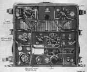
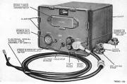
Made by Telefunken in Germany this is a low-power radio transmitter and receiver that was used in either ground or vehicle applications.
The equipment is an American design dating back to the end of WW2.
Made in the USA or under
license in Germany and France.
Frequency coverage : -
2 to 22 MHz Am or CW and has an RF output power of 1 to 15
watts.
Transmitter Section covers : -
2 to 3.6, 3.6 to 6.6, and 6.6 to 12 MHz continuously
tuneable
Or two pre-set channels.
AM & CW Hi-Lo Out-puts 7 or 1 Watt AM 15 or 5 Watt
CW.
The power amplifier uses 2E22 tubes ( valves )
Power supply required : -
580v DC @ 100ma
6.6v DC @ 2 Amps
120v DC @ 45ma
1.5v DC @ 500ma
6.9v DC @ 575ma.
|
|
|
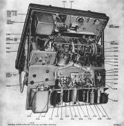 |
The Receiver Section covers
: -
2 to 3.6, 3.6 to 6.6, and 6.6 to 12 MHz
Continuously tuneable in 3 bands AM-CW
Intermediate Frequency 456 KHz
200 KHz Calibration Points
AF and RF Gain Controls
Headset jacks.
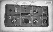
Power Supply : -
DY-88 Dynamotor Power Supply from : -
6v DC @ 29 Amp
12v DC @ 14 Amp
24v DC @ 6.7 AmpsOutputs : -
580v @ 100ma
105v @ 45ma
6.3v @ 2A
1.4v @ 500ma
6.3v @ 575ma
Mounted over the other rear wheel arch.
A padded metal box containing a complete set of spare valves (tubes) and lamps for the set are also carried in the vehicle, along with the headphones, microphone,
morse key and loudspeaker.
|
 |
|
Operation and
Technical
Data including Circuits &
Layouts
Details Below
As a Download
Click Here |
|
 |
AM-66-A RF Power Amp
For the ANGRC9 RT77-AN/GRC-9 radio set.
24 VDC input
Power output 100 Watts
Frequency Range 2-12 Mhz
Field Hand-crank Generator complete with Hand-crank, Legs, Seat and a
Canvas Bag.
Outputs : -
425v DC @ 15ma
105v DC @ 32ma
6.3v DC @ 2.5A
1.4v DC @ 465ma.
Four canvas straps secured the radio to its mounting bracket so it was easy to remove from the vehicle for portable field use, where it could be operated from batteries (receive only) or by connecting it to a hand operated generator.
Removed from its mounting it could be carried in a canvas rucksack.
The hand generator set was also carried in its own canvas holder, along with the aerial which was in four sections. |
 |
|
Operation and
Technical
Data including Circuits &
Layouts
Details Below
As a Download
Click Here |
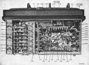
The Information Consists
of the
Following :-
- Operating Instructions
- Block Diagram
- Fault finding
- Receiver
- Top View Receiver
- Rear View Receiver
- Bottom View Receiver x 3
- Valve Data
- Transmitter
- Top View Transmitter
- Rear View Transmitter
- Bottom View Transmitter x 2
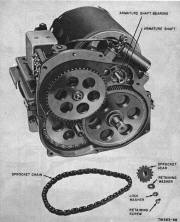
- Dynamotor Power Supply
- Bottom View Dynamotor Power Supply
- Rear View Dynamotor Power Supply
- Receiver Alignment
- Alignment points Top
- Alignment Points Bottom
- Transmitter Alignment
- Alignment Points Top
- Alignment Points Rear
- Circuit Diagram Transmitter
- Circuit Diagram Receiver
- Circuit Diagram Dynamotor
|
|
|
Operation and
Technical
Data including Circuits &
Layouts
Details Below
As a Download
Click Here |
Transceiver Transmitter Receiver.
Manuals are Available
Worldwide as a Download.
AN/GRC-9 AN/GRC-9A AN/GRC-9X AN/GRC-9Y
AN/GRC9A AN/GRC9X AN/GRC9Y AN/GRC9
ANGRC9 ANGRC 9 AN/GRC9
RT77 RT77A RT-77 RT-77A
Department of the Army Technical Manual TM 11-263
Department of the Air Force Technical Manual TO 31R2-2GRC9-1
Operation and Technical Data Including Circuits & Layouts
Total of 270 A4
Pages.
Manual 270 A4 pages worldwide : -
( For all Payment Options )
( Please Click the Payment Links Below )
|
|
We do all we can to provide
the very best that is available for you.
But in the unlikely event that any data should not be as you expected.
A refund is always available. Kind Regards Allen and Alanna. |
|


