|
HRO Radio
Communications Receiver Rx Manual
HRO-5 HRO-5T HRO-5R HRO-M HRO-MX
HRO-MRR HRO-MTM HRO-SR HRO-JR
HRO5 HRO5T HRO5R HROM HROMX
HROMRR HROMTM HROSR HROJR
|
|
This manual should also cover the
HRO-W HROW, as
the primary differences
between the
HRO-5T and HRO-W are the S-Meter and the Tropical Anti Fungal coating. |
|
Circuit Diagram, Service
Manual, Service
Information, Schematic Diagrams and Manuals |
|
For Repairing, Restoration and
Servicing of Vintage and Modern Electronic Equipment |
|
Manual and
Circuit
available
Details Below
As a Download
Click Here
|
|
Circuits
& Manuals
Military,
Radio, TV,
Amateur & Marine
World Wide Service
For
Lists Click Here
|
|
Use R/H scroll Bar
More information
below
Radio's For Sale
Click Here
Military and
Broadcast
Radio Ads Click
Here |
|
Military Radio Home
Click
Here If no Index to the left
|
HRO-5 HRO-5T HRO-5R HRO-M HRO-MX
HRO-MRR HRO-MTM HRO-SR HRO-JR
HRO5 HRO5T HRO5R HROM HROMX
HROMRR HROMTM HROSR HROJR
Should also cover the HRO-W HROW
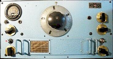
The HRO Comunication Receiver
was a high frequency super heterodyne suitable for CW and MCW reception
throughout the frequency range.
Frequency Coverage
50 to
430 kc/s and 480 to 30,000 kc/s in 9 bands. (coil sets)
Band 1 : -
50 to 100 kc/s.
Band 2 : - 100 to 200 kc/s.
Band 3 : - 180 to
430 kc/s.
Band 4 : - 480 to 960 kc/s.
Band 5 : - 900 to 2050 kc/s.
Band 6 : - 1.7 to4.0 Mc/s.
Band 7 : - 3.5 to 7.3 Mc/s.
Band 8 : -
7.0 to 14.4 Mc/s.
Band 9 : - 14.0 to 30.0 Mc/s.
|
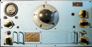
This HRO is Blue
An original paint job.
All the others I have
seen are Black.
|
The receiver uses a separate mains
power supply capable of supplying 240 volts DC at 70 milliamperes and 6.2
volts AC at 3.4 amperes, although lower plate voltages down to 135
volts may be used with some sacrifice in performance.
A separate
loudspeaker is required.
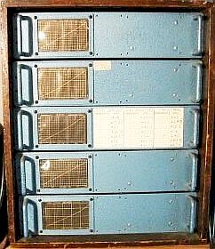
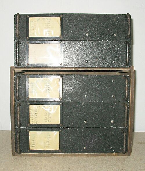
The band change is by plug in units, which are
housed in a separate wooden box as pictured when not in use.
The HRO is a
very stable receiver and hence was used extensively at listening stations
though out WW2 and for some time later.
The weight of the HRO Receiver including
the 9 coil sets is 51 lbs - 23.1kg. |

Matching HRO
Blue Coil Pack
|
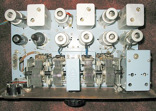
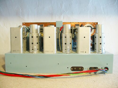
| HRO Chassis Top View |
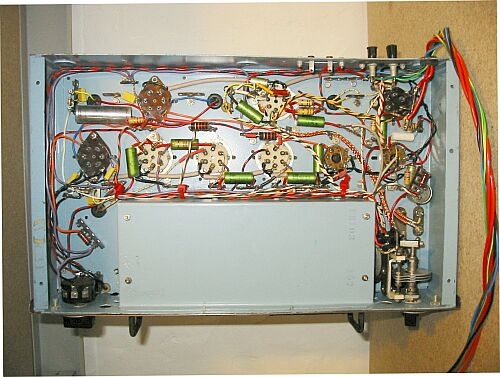
HRO Chassis Bottom View |
HRO Chassis Rear View |
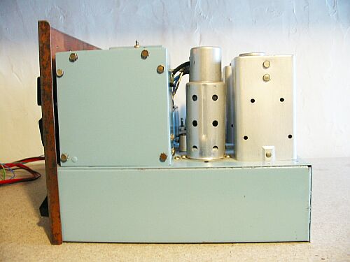
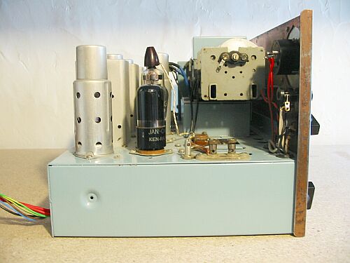
| HRO Chassis RH View |
HRO Chassis LH View |
HRO Coil Pack |
| The HRO Manual Contains the
Following : -
DESCRIPTION
Receiver
Power Unit
Loud Speaker
INSTALLATION
CIRCUIT DESCRIPTION
Special Feature
OPERATING INSTRUCTIONS
Controls
C.W. Reception
L.C.W. Reception
Reception With The Crystal filter
Measurement of Signal Strength
ALIGNMENT
Intermediate Frequency Amplifier Alignment
High Frequency Oscillator Alignment
RF Amplifier Alignment
Tracking of The H.F. Oscillator and R.F. Amplifier Circuits
Band Spread Alignment
MAINTENANCE FAILURES AND REMEDIES
TABULATION OF PARTS
JOINT ARMY-NAVY TYPE DESIGNATIONS
PHOTOGRAPHS
CIRCUIT DIAGRAMS
POWER UNIT TYPES
LOUD SPEAKER TYPES
ADDENDA OR NOTES
|
Manual and
Circuit
available
Details Below
As a Download
Click Here |
Manual covering
the : -
HRO-5 HRO-5T HRO-5R HRO-M HRO-MX HRO-MRR HRO-MTM HRO-SR HRO-JR.
HRO5 HRO5T HRO5R HROM HROMX HROMRR HROMTM HROSR HROJR.
This manual should also cover the HRO-W HROW, as the
primary differences between the
HRO-5Tand HRO-W are the S-Meter and the Tropical Anti Fungal coating.
Manuals are Available Worldwide as a Download.
Manual 51 A4 pages worldwide
( For all Payment Options )
( Please Click the Payment Links Below ) |
|
We do all we can to provide
the very best that is available for you.
But in the unlikely event that any data should not be as you expected.
A refund is always available. Kind Regards Allen and Alanna. |
|