|
Marconi TF995A &
TF995A/1
TF 995A & TF 995A/1 FM AM Signal
Generator
|
|
Circuit Diagram, Service
Manual, Service
Information, Schematic Diagrams and Manuals |
|
For Repairing, Restoration and
Servicing of Vintage and Modern Electronic Equipment |
|
Manual and
Circuit
available
Details Below
As a Download
Click Here
|
|
Circuits
& Manuals
Military,
Radio, TV,
Amateur & Marine
World Wide Service
For
Lists Click Here
|
|
Use R/H scroll Bar
More information
below
Radio's For Sale
Click Here
Military and
Broadcast
Radio Ads Click
Here |
|
Military Radio Home
Click
Here If no Index to the left
|
Marconi TF995A & TF995A/1 FM AM
Signal
Generator
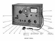
Signal Generator Type TF 995A is a.c. mains operated and transportable.
This generator has a
crystal standardized frequency range covering from 13.5 to 216 Mc/s in four
bands.
Its open circuit output level is variable in 1db steps, from a
minimum of 0.1 micro volts to a maximum of 100 mV at 52 ohms and 200 mV at 75 ohms.
The output may be c.w, frequency modulated, amplitude modulated, or
simultaneously both frequency and amplitude modulated.
|

|
The modulation obtained either from an internal 1,000-c/s oscillator or from an external source, is variable to
maximum frequency deviations ranging from 25 to 600 kc/s for f.m. and to depths up to
5% for a.m.
Power Unit
A full-wave rectifier provides all d.c. h.t. requirements; in the case of the reactor
and r,f. oscillator valves the h.t. is neon stabilized.
The primary of the
transformer is tapped to allow for operation from 100 to 150 volts or 200 to 250
volts.
R.f. filtering is introduced into the a.c.
input circuit. |
Manual and
Circuit
available
Details Below
As a Download
Click Here
|
| The Information Consists
of the
Following
The Manual contains all circuits for the : -
Marconi FM AM Signal
Generator TF995A
DESCRIPTION
GENERAL
DESIGN DETAILS
OPERATION
INSTALLATION
MAINS INPUT ARRANGEMENTS
Supply voltages, 200 to 250 volts
Supply voltages, 100 to 150 volts
SWITCHING ON AND WARMING UP
CONNECTING TO EQUIPMENT UNDER TEST
TUNING
The Crystal Calibrator and its use in standardizing the frequency scale
Use of the incremental tuning dial
SETTING UP FOR C.W. OR MODULATED OUTPUT
Continuous Wave
Amplitude Modulation
Frequency Modulation
Simultaneous Frequency and Amplitude Modulation
R.P. OUTPUT ARRANGEMENTS
Outputs from 1 uV to 100 mV at 52 and 75 ohms
Outputs from 2 uV to 200 mV at 75 ohms only
Outputs from 0.1 uV to 10 mV at 52 and. 75 ohms
Output in terms of voltage developed across an external load
Matching to external loads other than 52 or 75 ohms
Matching to balanced loads
SYNCHRONIZING - SIGNAL
OPERATIONAL SUMMARY
MAINTENANCE
GENERAL
REPLACEMENT OF VALVES AND CRYSTALS
WORKING VOLTAGES
ACCESS TO ENCLOSED SUB-ASSEMBLIES
R.F. Unit
Fine Attenuator
Coarse Attenuator
Mains Input Filter Unit
Power Unit
REPLACEMENT OF COMPONENTS OF SPECIALLY SELECTED
VALUE
SCHEDULE OF TESTS
Apparatus Required
Insulation
Hum Level
Crystal Oscillator
Basic Oscillator
Frequency Multipliers
Accuracy of the R.F. Output Voltage
Modulation Oscillator
Frequency Deviation
F.M. Distortion
Deviation Range Adjustments
Deviation Monitor Circuit
High Deviation
External F.M
Internal A.M
External A.M.
Spurious A.M.
APPENDICES
VALVE REPLACEMENT DATA
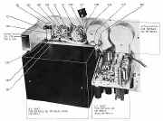
COMPONENT LAYOUT ILLUSTRATIONS
SPARES ORDERING SCHEDULE WITH CIRCUIT REFERENCES
BLOCK SCHEMATIC DIAGRAM
COMPLETE CIRCUIT DIAGRAM
DECIBEL CONVERSION TABLE
|

|
|
Manual and
Circuit
available
Details Below
As a Download
Click Here
|
|

|
If your model is the TF 995A it
will have a valve line up as below
If it is the TF
995A/1 it has
an extra valve a 12AT7 double triode
Six: Type EF95 Pentodes.
Two: Type 6AK6 Pentodes.
One: Type 6AU6 Pentode
One: Type QS15O/15 Voltage Stabilizer.
One: Type 5Z4G Full Wave Rectifier,
One: Type D77 Double Diode.
|
If your model is the TF 995A/5 it will have a valve line up as below
Six; Type 6AK5, Pentodes.
One: Type 6AK6, Pentode.
One: Type 6AL5, Double Diode.
One: Type 6AU6, Pentode.
One: Type EF86, Pentode.
Two: Type 12AT7, Double Triodes.
One: Type 5Z4G Full Wave Rectifier.
One: Type OA2, Voltage Stabilizer.
One: Type 5651, Voltage Stabilizer.
|
Marconi TF995A FM
AM Signal Generator 1954 vintage and TF995A/1 1955
For the TF995A/5 a later 1960 model Click Here
Manuals are Available Worldwide as a
Download.
Manual including circuit
95 pages
Manual 95 A4 pages worldwide
( For all Payment Options )
( Please Click the Payment Links Below )
|
|
We do all we can to provide
the very best that is available for you.
But in the unlikely event that any data should not be as you expected.
A refund is always available. Kind Regards Allen and Alanna. |
|


