|
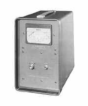
Marconi Power Meter
TF
1152A TF 1152A/1 TF1152A TF1152A/1
|
|
Circuit Diagram, Service
Manual, Service
Information, Schematic Diagrams and Manuals |
|
For Repairing, Restoration and
Servicing of Vintage and Modern Electronic Equipment |
|
Manual
Circuit and
Operation Instructions
Details Below
As a Download
Click Here
|
|
Circuits
& Manuals
Military,
Radio, TV,
Amateur & Marine
World Wide Service
For
Lists Click Here
|
|
Use R/H scroll Bar
More information
below
Radio's For Sale
Click Here
Military and
Broadcast
Radio Ads Click
Here |
|
Military Radio Home
Click
Here If no Index to the left
|
Marconi Power Meter
TF
1152A TF 1152A/1 TF1152A TF1152A/1
The TF 1152A and TF 1152A/1 are
direct reading absorption watt meters for use at any frequency up to 500 Mc/s.
Each has two measurement ranges of 10 and 25 watts full scale.
They differ only in input impedance, which is 75 ohms for TF 1152A and 50 ohms for TF 1152A/l.
These instruments measure mean power irrespective of waveform, the power contained in all harmonics up to 500 Mc/s being correctly summed with the power in the fundamental.
The meters will therefore indicate the correct increase in power when amplitude modulation is applied to a c.w. input and thus percentage depth of modulation can be calculated.
Another application is the measurement of the mean power output of pulse transmitters or modulators.
The insulation of the input circuit is rated at 500 volts and this allows the application of peak powers of up to
3.3 kW for the 75-ohm version and 5 kW for the 50-ohm version.
Their small size and light weight, and their freedom from internal batteries or external power
supplies, make these instruments well suited for mobile use.
|

|
| The Manual Contains the
Following
SCHEDULE OF PARTS SUPPLIED
DATA SUMMARY
DESCRIPTION
GENERAL
DESIGN DETAILS
OPERATION
GENERAL
CONNECTIONS
MAKING A MEASUREMENT
DETERMINATION OF MODULATION DEPTH
MAINTENANCE
GENERAL
REMOVAL AND REPLACEMENT OF COMPONENTS
Removal of Case
The Thermocouple
The Load Resistor
SCHEDULE OF TESTS
Apparatus Required
Preliminary Checks
Standing Wave Ratio
Calibration Accuracy at L.F.
Calibration Accuracy at R.F.
COMPONENT LAYOUT ILLUSTRATIONS
EXTERNAL
INTERNAL
ENLARGED VIEW OF THERMOCOUPLE CIRCUIT
SPARES ORDERING SCHEDULE
CIRCUIT DIAGRAM
APPENDICES
DECIBEL CONVERSION TABLE
ILLUSTRATIONS IN TEXT
FUNCTIONAL DIAGRAM
ADMITTANCE CHARACTERISTIC
TEMPERATURE CORRECTION GRAPH
ADJUSTING SCREW POSITIONS
|
Manual
Circuit and
Operation Instructions
Details Below
As a Download
Click Here
|
Marconi Power
Meter
TF 1152A TF 1152A/1 TF1152A TF1152A/1
Manuals are Available Worldwide as a
Download.
Manual containing 20 pages including the Circuit with Component
values.
Manual 20 A4 pages worldwide
( For all Payment Options )
( Please Click the Payment Links Below ) |
|
We do all we can to provide
the very best that is available for you.
But in the unlikely event that any data should not be as you expected.
A refund is always available. Kind Regards Allen and Alanna. |
|


