|
R107 Receiver Reception
Set
Communication Receiver
|
|
Circuit Diagram, Service
Manual, Service
Information, Schematic Diagrams and Manuals |
|
For Repairing, Restoration and
Servicing of Vintage and Modern Electronic Equipment |
|
Manual and
Circuit
Plus Additional Articles
available
Details Below
As a Download
Click Here
|
|
Circuits
& Manuals
Military,
Radio, TV,
Amateur & Marine
World Wide Service
For
Lists Click Here
|
|
Use R/H scroll Bar
More information
below
Radio's For Sale
Click Here
Military and
Broadcast
Radio Ads Click
Here |
|
Military Radio Home
Click
Here If no Index to the left
|
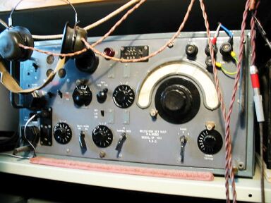
Reception Set R107
The Reception Set R107 was a receiver
designed for CW and RT reception and was usually employed in conjunction
with Wireless Sets No12 and 33.
The Frequency Range was 1.2 to 17.5 Mc/s in
three overlapping bands.
Band 1 : - 17.5 to 7 Mc/s.
Band 2 : -
7.25 to 2.9 Mc/s.
Band 3 : - 3.0 to 1.2 Mc/s.
The set was
designed for operation from a 12 volt accumulator or alternatively
from 100/250 volts (50 c/s AC).
Change over from DC to AC operation was
accomplished by means of a two-way switch in the power-chassis.
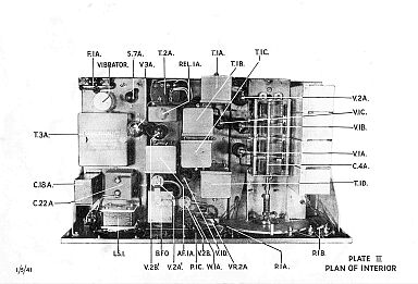
The
complete apparatus comprises of three separate chassis units i.e. RF,
IF/AF and Power. |
|
These are mounted on a steel framework
and a sheet steel panel carries the receiver controls.
Connection
between the three units is achieved by means of tag-boards.
Circuit
Description
A nine valve (eight plus rectifier) super-heterodyne
circuit is employed.
The valves were indirectly heated (6.3v heaters) and
were fitted with International Octal bases.
There are four RF
pentodes (ARP34), four double-diode-triodes (AR21) and a full wave
rectifying valve (6x 5G).
The circuit was arranged as follows.
An RF
stage was coupled by means of a band-pass filter to a mixer stage with a
separate 1st Local Oscillator. |
|
The intermediate frequency signal (465
kc/s) thus produced was amplified by two IF stages which were followed by
the combined signal detector AVC and AF stage.
An
output stage and Beat Frequency Oscillator complete the circuit.
Power
Consumption
DC 3.25 amps at 11.5 volts. AC 50 volt-amps. |
Manual and
Circuit
Plus Additional Articles
available
Details Below
As a Download
Click Here |
| The R107
Receiver Manual Contains the
Following
GENERAL DESCRIPTION
Frequency Range
Performance
Power Supply
Aerial
Circuit and Controls
Panel Sockets
Panel Jacks
Construction
Weight and Dimensions
WORKING INSTRUCTIONS
Preliminary
Valves used
Connecting up power supply
Battery operation
A.C. mains operation
Operating the receiver
For R.T.
For C .W. reception
Use of the crash limiter
MAINTENANCE
General notes on maintenance
Test figures
Receiver
Receiver test panel readings
Point to point resistance tests
Voltage tests
Receiver sensitivity tests
General
2nd A.F. stage
1st A.F. stage
2nd 1.F. stage
1st I.F. stage
F.C. stage
Overall Sensitivity
Beat frequency oscillator
Location of faults
A.F. and preceding stages
R .F. Unit
Special note on valve faults
Inspection of wiring and coils
Receiver faults
Information for guidance of R.A.0.C . workshops
Notes on alignment of circuits
Dismantling Instructions
Special receiver faults
DIAGRAMS
Reception Sets R.107 Circuit diagram.
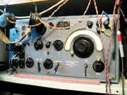
Front view of panel.
Plan view of interior.
Connections to Sender No. 12
Connections to Sender No.33
PLATES
Front Panel
Plan of Interior
Tuning Unit
Underside of R.F. Chassis
Underside of I.F. Chassis
Interior of B.F.O. Unit.
Underside of Power Unit
COMPONENTS LIST
Condensers
Resistors
Inductors
Switches
Transformers
Miscellaneous
Valves
Coding for Condensers and Resistances
|
|
|
Manual and
Circuit
Plus Additional Articles
available
Details Below
As a Download
Click Here |
|

|
R107
Receiver
The Manual contains 68 A4 pages including Circuits
Component lists and Layouts.
Plus 13 pages of Additional Articles if
required.
Manuals are Available Worldwide as a
Download.
Manual
68 A4 pages worldwide
Additional Articles 13 pages worldwide
Or both the Manual 68 pages Plus 13 pages of Additional Articles
as below a Total of 81 pages
Manual
81 A4 pages worldwide, saving round £5.00
( For all Payment Options )
( Please Click the Payment Links Below )
Details of Additional Service Articles available Below
Click Here |
|
We do all we can to provide
the very best that is available for you.
But in the unlikely event that any data should not be as you expected.
A refund is always available. Kind Regards Allen and Alanna. |
|
Manuals are Available
Worldwide as a Download
Thank you for your interest. Allen
and Alanna G0RIT
Should you wish to purchase
 For Worldwide Prices Payment Options and Delivery
Details
For Worldwide Prices Payment Options and Delivery
Details
Manual Only
For Worldwide Prices Payment Options and Delivery
Details
Additional Articles Only
For Worldwide Prices Payment Options and Delivery
Details
Special Offer Manual and Additional
Articles


|
|
R107
Additional Articles 13 pages |
Developing the R107
Bandspread on the R107
The R107 RF IF packs
Improving the R107 for SSB reception
The R107 receiver
|
The R107
Receiver
The Manual contains 68 A4 pages including Circuits
Component lists and Layouts.
Plus 13 pages of Additional Articles if
required.
Manuals are Available Worldwide as a
Download.
Manual
68 A4 pages worldwide
Additional Articles 13 pages worldwide
Or both the Manual 68 pages Plus 13 pages of Additional Articles
as below a Total of 81 pages
Manual
81 A4 pages worldwide, saving round £5.00
( For all Payment Options )
( Please Click the Payment Links Below )
Details of Additional Service Articles available
Above
Click Here |
|
We do all we can to provide
the very best that is available for you.
But in the unlikely event that any data should not be as you expected.
A refund is always available. Kind Regards Allen and Alanna. |
|
Manuals are Available
Worldwide as a Download
Thank you for your interest. Allen
and Alanna G0RIT
Should you wish to purchase
For Worldwide Prices Payment Options and Delivery
Details
Manual Only
For Worldwide Prices Payment Options and Delivery
Details
Additional Articles Only
For Worldwide Prices Payment Options and Delivery
Details
Special Offer Manual and Additional
Articles
|
|