|
Racal Frequency Counter
Type 9024
|
|
Circuit Diagram, Service
Manual, Service
Information, Schematic Diagrams and Manuals |
|
For Repairing, Restoration and
Servicing of Vintage and Modern Electronic Equipment |
|
Manual
Circuit and
Operation Instructions
Details Below
As a Download
Click Here
|
|
Circuits
& Manuals
Military,
Radio, TV,
Amateur & Marine
World Wide Service
For
Lists Click Here
|
|
Use R/H scroll Bar
More information
below
Radio's For Sale
Click Here
Military and
Broadcast
Radio Ads Click
Here |
|
Military Radio Home
Click
Here If no Index to the left
|
| Racal Frequency Counter
Type 9024 INTRODUCTION
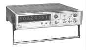
The Type 9024 is a compact, Lightweight Frequency Period Meter styled in the Racal 9000 series image,
being slim-line and of full rack width.
It has a frequency measuring capability covering the range 10Hz to 600MHz,
this is achieved using two input channels each with its own switched attenuator.
Signals in the range 10MHz to 600MHz are applied to the Channel ‘A’ input where a Pre-Scaler Assembly of advanced design provides decade division.
The Channel ‘B’ input is used when measuring frequency in the range
l0Hz to 60 MHz and also for Period Measurement in the range 10 Hz to 3 MHz.
|

|
| The Manual Contains the
Following :-
TECHNICAL SPECIFICATION
DESCRIPTION OPERATION AND MAINTENANCE
GENERAL DESCRIPTION
PREPARATION FOR USE
Power and Earth Connections
Removal of case
Self Check Procedure
Using an External Frequency Standard
Removal of Plug in Boards
Fuselink Data
OPERATING
Description of Controls
OPERATING PROCEDURES
Frequency Measurement
Average Period Measurement
Operation with Active Probe
Connection of External Frequency Standard
1 MHz Output
PRINCIPLES OF OPERATION
Frequency Measurement
Period Measurement
Timebase and Control
Frequency Standard
Channel Selection
TECHNICAL DESCRIPTION
Attenuator and Pre-amplifier 1 1-0339
Attenuator 19-0620
Amplifier Divider Assembly 19-0630
Amplifier Gating Assembly 19—0379
Frequency Standard Oscillator Assembly
Timebase Divider Assembly 19—0352
Control Circuit Assembly 19—0356
Readout and Display
High Speed Decade Assembly 19—0460
Standard Readout Assembly
Power Supply Assembly
Power Switching
MAINTENANCE
List of Test Equipment required
Use of Test Equipment
Power Supply Check
Performance Tests and Setting—Up Procedures
ILLUSTRATIONS
Simplified Block Diagram
Frequency Measurement
Period Measurement
Control Circuit Waveforms
Timing Waveforms H.S. Decade 19-0460
Timing Waveforms: Standard Readout Decade
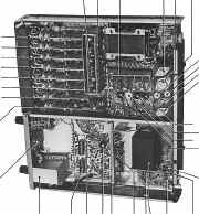
Service View: Chassis Upperside
PARTS LIST
CIRCUIT DIAGRAMS AND LAYOUTS
Circuit: Pre—Amplifier Assembly
Circuit: Oscillator Assembly
Circuit: Power Supply Assembly.
Layout: Attenuator Assembly
Layout: Pre—Amplifier Assembly
Layout: Timebase Divider Assembly
Circuit: Timebase Divider Assembly
Layout: Control Circuit Assembly
Circuit: Control Circuit Assembly
Layout: Amplifier Gating Assembly.
Circuit: Amplifier Gating Assembly
Layout: Power Board
Layout: Oscillator Board
Layout: Standard Readout Assembly.
Circuit: Standard Readout Assembly
Layout: High Speed Decade Assembly
Circuit: High Speed Decade Assembly
Layout: Attenuator
Circuit: Attenuator
Layout: Remote Control Assembly
Circuit: Remote Control Assembly
Layout: Amplifier Divider Assembly
Circuit: Amplifier Divider Assembly
Layout: Motherboard Assembly
Circuit: Interconnections Type 9024
APPENDICES AND CHANGE INFORMATION
|

|
|
Manual
Circuit and
Operation Instructions
Details Below
As a Download
Click Here
|
Racal Frequency
Counter
Type 9024
Manuals are Available Worldwide as a
Download.
Manual containing 119 pages including the Circuits with Component
lists and layouts.
Manual 119 A4 pages worldwide
( For all Payment Options )
( Please Click the Payment Links Below )
|
|
We do all we can to provide
the very best that is available for you.
But in the unlikely event that any data should not be as you expected.
A refund is always available. Kind Regards Allen and Alanna. |
|


