|
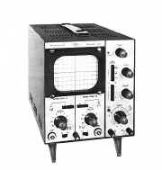
Telequipment Oscilloscope D52 &
S52
|
|
Circuit Diagram, Service
Manual, Service
Information, Schematic Diagrams and Manuals |
|
For Repairing, Restoration and
Servicing of Vintage and Modern Electronic Equipment |
|
Maintenance
Manual with
Circuits and
Operation Instructions
Details Below
As a Download
Click Here
|
|
Circuits
& Manuals
Military,
Radio, TV,
Amateur & Marine
World Wide Service
For
Lists Click Here
|
|
Use R/H scroll Bar
More information
below
Radio's For Sale
Click Here
Military and
Broadcast
Radio Ads Click
Here |
|
Military Radio Home
Click
Here If no Index to the left
|
Telequipment D52
& S52 Oscilloscope
Manuals
also available for the following models :-
S22, D31, D31R, S31, S31R, D32,
S32A, S32AR, D43,
D43R, S43, D51, S51,
D52, S52, D54, D54R,
D56, D61,
D61A, DM63, DM64, D65, D66,
D67, D67A, D80, D83,
D1010, D1011, D1015, D1016 & Serviscope Minor.
Click
Here
GENERAL DESCRIPTION
The S 52 and D 52 Serviscopes are two instruments using very similar circuits and components.
The D 52 uses a 5” flat faced split beam C .R. T. to provide a dual trace instrument, while the S 52 uses a 5” flat faced single beam C. R. T. with identical vertical and horizontal deflection amplifiers to provide a large display X-Y oscilloscope.
Both instruments use a common time base and power supply. The following details apply to both instruments, any differences between them being separately described.
SPECIFICATION
Vertical Deflection Amplifier
Each consists of a four stage, balanced, DC coupled amplifier, compensated for optimum pulse response and having no overshoot.
Frequency Response & Sensitivities
D 52 ( DC - 6 Mc/s at 100 mV/cm
(DC - 1 Mc/s at 10 mV/cm
S 52 ( DC - 3 Mc/s at 100 mV/cm
( DC - 1 Mc/s at 10 mV/cm
|

|
|
The Manual Contains the
Following :-
GENERAL DESCRIPTION
1. General Description
2. Specification
3. First Time Operation
4. Sweep Controls
5. Deflection Amplifier Controls
6. Additional Facilities
TIME BASE AND ASSOCIATED CIRCUITS
1. The Trigger Circuit
2. The Time Base and Horizontal Deflection Amplifier
3. Time Base Controls
THE VERTICAL DEFLECTION CIRCUITS
1. Vertical Deflection Amplifier
2. Circuit Description
THE CATHODE RAY TUBE CIRCUIT (D 52)
1. General Description
2. Circuit Description
THE CATHODE RAY TUBE CIRCUIT (S 52)
1. General Description
2. Circuit Description
POWER SUPPLIES
1. General Description
2. Circuit Description
MAINTENANCE, SERVICING AND SETTING-UP PROCEDURE
1. General
2. Amplifier Test Procedure
3. Time Base Test Procedure
4. Trigger Circuit
5. Sweep Generator and X Amplifier
6. CRT Circuit Adjustments
7. Power Supply Circuit Adjustments
COMPONENTS LIST
ILLUSTRATIONS
SERVISCOPE TYPE D 52
Y AMPLIFIER PRINTED CIRCUIT BOARD
TIME BASE AND H.T. PRINTED CIRCUIT BOARD
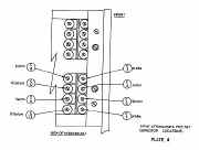
INPUT ATTENUATOR CAPACITOR LOCATION
LIST OF FIGURES
TRIGGER CIRCUIT
TIME BASE & HORIZONTAL AMPLIFIER
TIME/CM SWITCH
INPUT ATTENUATOR CAPACITOR LOCATION
VERTICAL AMPLIFIER (D 52)
VERTICAL AMPLIFIER (S 52)
CRT CIRCUIT (D 52)
CRT CIRCUIT (S52)
POWER SUPPLY (D 52)
POWER SUPPLY (5 52).
|

|
|
Maintenance
Manual with
Circuits and
Operation Instructions
Details Below
As a Download
Click Here
|
Telequipment D52
& S52 Oscilloscope
Manuals are Available Worldwide as a
Download.
The
Manual contain 67 pages including Circuits,
Component lists and printed Board Layouts
Manual
67 A4 pages worldwide
( For all Payment Options )
( Please Click the Payment Links Below ) |
|
We do all we can to provide
the very best that is available for you.
But in the unlikely event that any data should not be as you expected.
A refund is always available. Kind Regards Allen and Alanna. |
|


