|
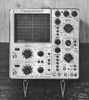
Telequipment Oscilloscope D67
|
|
Circuit Diagram, Service
Manual, Service
Information, Schematic Diagrams and Manuals |
|
For Repairing, Restoration and
Servicing of Vintage and Modern Electronic Equipment |
|
Maintenance
Manual with
Circuits and
Operation Instructions
Details Below
As a Download
Click Here
|
|
Circuits
& Manuals
Military,
Radio, TV,
Amateur & Marine
World Wide Service
For
Lists Click Here
|
|
Use R/H scroll Bar
More information
below
Radio's For Sale
Click Here
Military and
Broadcast
Radio Ads Click
Here |
|
Military Radio Home
Click
Here If no Index to the left
|
Telequipment D67 Oscilloscope
Manuals
also available for the following models :-
S22, D31, D31R, S31, S31R, D32,
S32A, S32AR, D43,
D43R, S43, D51, S51,
D52, S52, D54, D54R,
D56, D61,
D61A, DM63, DM64, D65, D66,
D67, D67A, D80, D83,
D1010, D1011, D1015, D1016 & Serviscope Minor.
Click
Here
The D67 is a 25 MHz, all solid state dual-trace oscilloscope. An 8 x 10 cm mesh CRT provides a bright and clear display.
The dual-trace vertical system displays either channel separately, adds channels algebraically, alternates between channels or chops between channels at 80 kHz rate.
The delayed sweep feature permits close examination of any part of a complex waveform and allows for an accurate time measurement of the input waveform.
The solid state design, using FET input circuitry, provides minimum drift and fast stabilization time.
|

|
|
The Manual contains the following
:-
Specification
Cathode Ray Tube (CRT)
Cooling
Front Panel outputs
Horizontal system
Power requirements
Size
Temperature limits
Trigger
Vertical system
Weight
Operating Instructions
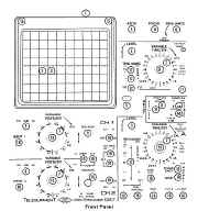
Controls and Connectors
Connectors, input & output
CAT
Delayed Sweep ‘B’
Horizontal display
Main Sweep ‘A’
Vertical Display Operation
Pre-operating checks
Circuit descriptions
Attenuators
Horizontal amplifier
Power supplies
Timebases
Triggers
Unblanking amplifier
Vertical Amplifier
|

|
Maintenance & Calibration
Access to interior
CRT removal & replacement
General
Location of Preset Controls
Mechanical
Calibration
CRT
Horizontal amplifier
Initial setting
Power supply
Preliminary
Probe
Sweep Trigger ‘A’ (Main)
Sweep ‘A’ generator
Sweep Trigger ‘B’ (Delayed)
Sweep ‘B’ generator
Vertical amplifier
Component List
Assembly
Electrical
Mechanical
Circuit Diagrams
Attenuators
Block diagram
C.R.T. Circuit
Component Reference
PC No 75
PC No76
PC No 88
Power supply
Timebase ‘A’
Timebase ‘B’
Time/Div
Trigger ‘A’
Trigger ‘B’
Unblanking Amplifier
Waveform diagram
‘X’ Amplifier
‘Y’ input & Channel switching
‘Y’ output & Trigger pre-amplifier |
Maintenance
Manual with
Circuits and
Operation Instructions
Details Below
As a Download
Click Here
|
Telequipment
D67 Oscilloscope
Manuals are Available Worldwide as a
Download.
Manual including circuits 78 pages
Manual
78 A4 pages worldwide
( For all Payment Options )
( Please Click the Payment Links Below ) |
|
We do all we can to provide
the very best that is available for you.
But in the unlikely event that any data should not be as you expected.
A refund is always available. Kind Regards Allen and Alanna. |
|


